

Duck Pond Redneckery
- Thread starter Duck
- Start date


 .......









Similar threads


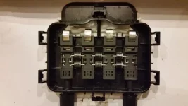
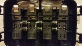


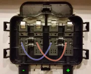
Schottky Diodes.@Hammer166 This is inside the plastic bottles on the back of one of the solar panels.
I don't know if @Blood has popped the cover off of one yet.
View attachment 36104
Looks like 4 individual circuits that would be 7.5 volts each?
But what are those cylinder shaped things?
Diodes?
View attachment 36105
Reverse current and discharge protection[edit]
Because of a Schottky diode's low forward voltage drop; less energy is wasted as heat, making them the most efficient choice for applications sensitive to efficiency. For instance, they are used in stand-alone ("off-grid") photovoltaic (PV) systems to prevent batteriesfrom discharging through the solar panels at night, called "blocking diodes". They are also used in grid-connected systems with multiple strings connected in parallel, in order to prevent reverse current flowing from adjacent strings through shaded strings if the "bypass diodes" have failed.
Plain ol' diode.... the schottky variety just has a lower forward voltade drop to minimize how much drop you get between the solar cell and the panel terminal.Schottky Diodes.
per wiki:
Do I need to post the fucking spec sheet showing that part number is a Schottky?Plain ol' diode.... the schottky variety just has a lower forward voltade drop to minimize how much drop you get between the solar cell and the panel terminal.
Outer conduct pairs?Clip out the middle diodes pull power off the outer conduct pairs, and you'll have 2 15+V power supplies.


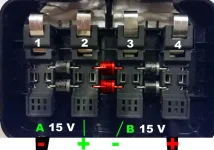
I think the way the diodes are installed, each block has two connections and not just one. I think you'll 7.5v across the left and right pins of each block. So in your drawing, the red wire needs to be moved over to the opposite side of the same block on both ends.Actually I'll dumb down the photoshopping....
So if I do this,... Notice I blacked out the center diodes,..... it will simply convert the panel to 15 volts while maintaining the same wattage, using the existing output cables?
View attachment 36109

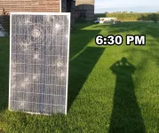
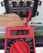
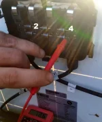
So I got behind on my laundry... sue me.Looks like your wearing a f'ing dress there Nancy

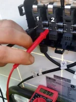
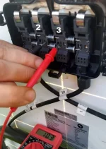
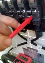
I think rather than being wired as 4 sets of 15cells, it's set up as 3 sets of 20 cells. That would explain those readings. And remember that is open circuit voltage. Rig up some leads to connect 2 buses to a battery and see what you get for voltage then.Anyhoo, buses 1 & 2 produce 9.2 volts in this amount of light, while 3 & 4 produce 8.3 volts.
With the whole panel producing roughly 27.7 volts total I can't seem to get (roughly) 13.85 volts anywhere. I don't get it..
