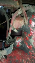
Duck Pond Redneckery


Update:

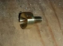
I made a replacement brass screw myself.

I found a piece of 3/8" solid brass rod and cut a 2" piece off.

Chucked it into the drill press and used my cross-slide vise to hold a file and basically had a redneck lathe.

I filed it down until it was small enough to get it into an 8-32 die to cut the threads.

Then I put it in the regular vise and cut the fatter part of the rod down leaving 3/16" for the head.

Holding it still with a hose clamp I used a 3/8" drill bit to dig out the bowl shape, then finally I cut the screwdriver slot with an air cutoff wheel and a small file made for sharpening chain saws.

20170410_184231~2.webp


Actually that's a load of bullshit. The screw came with the electronic ignition kit that finally showed up in the mail today.
 
Update:

I made a replacement brass screw myself.

I found a piece of 3/8" solid brass rod and cut a 2" piece off.

Chucked it into the drill press and used my cross-slide vise to hold a file and basically had a redneck lathe.

I filed it down until it was small enough to get it into an 8-32 die to cut the threads.

Then I put it in the regular vise and cut the fatter part of the rod down leaving 3/16" for the head.

Holding it still with a hose clamp I used a 3/8" drill bit to dig out the bowl shape, then finally I cut the screwdriver slot with an air cutoff wheel and a small file made for sharpening chain saws.

View attachment 39847


Actually that's a load of bullshit. The screw came with the electronic ignition kit that finally showed up in the mail today.
Good job! However I was looking forward to having a friend that had a 3D printer.:biglaugh:
 
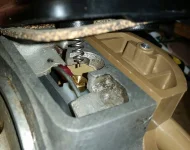
Here's a visual on why the concave head brass screw.

20170410_204651~2.webp

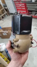
Anyone ever seen a distributor like this, sideways, with the coil mounting directly on top?

20170410_210232.webp

20170410_210742.webp
 
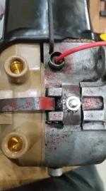
Here's how the ignition timing works.

Supposed to be TDC so you center these marks.

20170410_210315.webp

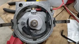
Inside the distributor this round plate that holds the points (now the magnetic thing) rotates a few degrees either way when that nut is loose.

20170410_204324.webp

There are no timing marks on the crankshaft pulley or the block. I don't know if timing lights were even invented yet in 1945.
 
Here's how the ignition timing works.

Supposed to be TDC so you center these marks.

View attachment 39853

Inside the distributor this round plate that holds the points (now the magnetic thing) rotates a few degrees either way when that nut is loose.

View attachment 39852

There are no timing marks on the crankshaft pulley or the block. I don't know if timing lights were even invented yet in 1945.
a farmer may not have had a timing light. but a simple light bulb set up would have done the job, as the light bulb would have flashed at firing.

another way to have checked the timing, and "be close" would have been to high idle the engine, say at least about 800 RPM, then slightly rotate to distributor in either direction. a smoother idle would have been an indication of a close timing of the engine.


glad to see you did away with the old points set up.
 
another way to have checked the timing, and "be close" would have been to high idle the engine, say at least about 800 RPM, then slightly rotate to distributor in either direction. a smoother idle would have been an indication of a close timing of the engine.

Ding! We have a winner.
 
a farmer may not have had a timing light. but a simple light bulb set up would have done the job, as the light bulb would have flashed at firing.

another way to have checked the timing, and "be close" would have been to high idle the engine, say at least about 800 RPM, then slightly rotate to distributor in either direction. a smoother idle would have been an indication of a close timing of the engine.


glad to see you did away with the old points set up.
Not the way this thing is designed... Unless you don't mind losing your arm. o_O

That screw came out pretty nice. All with hillbilly tools too!
Go back and read the fine print. ;)
 
The wiring diagram explaining how to hook up the 12 volt conversion kit refers to the ammeter. "The red wire goes to the ammeter and the white wire goes from the ammeter to the starter solenoid, blah blah blah...

The posts on the ammeter don't even exist.. It's like they rusted off or something and someone rewired it to a resistor. An old rusty resistor...

And the starter solenoid is not an actual solenoid... You push the starter button and you physically join two electrodes that start it. There are only two terminals on it. One from the battery and the other to the starter. o_O

So much stuff omitted.

And the instructions for the electronic ignition kit actually omits the step where you install the electronic ignition kit... :rolleyes:
 
Not the way this thing is designed... Unless you don't mind losing your arm. o_O

Go back and read the fine print. ;)
that's right, i forgot the fan blade location to the distributor........you could just bolt up the fan pulley (if the fan can be separated from it, then set your timing, when done, install the fan..????

or just leave it off..in the short amount of time you would be idling that engine, it shouldn't get that hot.

heck, you can even install an electric cooling fan, for a few dollars more. might actually keep that engine cooler.
 
The wiring diagram explaining how to hook up the 12 volt conversion kit refers to the ammeter. "The red wire goes to the ammeter and the white wire goes from the ammeter to the starter solenoid, blah blah blah...

The posts on the ammeter don't even exist.. It's like they rusted off or something and someone rewired it to a resistor. An old rusty resistor...

And the starter solenoid is not an actual solenoid... You push the starter button and you physically join two electrodes that start it. There are only two terminals on it. One from the battery and the other to the starter. o_O

So much stuff omitted.

And the instructions for the electronic ignition kit actually omits the step where you install the electronic ignition kit... :rolleyes:
well, you already know, you can get an aftermarket amp gauge. i'd say an amp gauge would be better than that resistor. as it is, that resistor can of course be another reason why the tractor does not start right up. you may not know the resistance value of what's in there now.
 
WTF is this now?

Yesterday's Tractors - Recommendations for 12 Volt Conversions

Starter

The starter will be unaffected by the change from positive to negative ground (it will rotate the same direction) and generally will tolerate the increased voltage, assuming the starter is in good working condition.

How can reversing the polarity on a DC motor not reverse the rotation? :confused-96:

It's a brush type motor. At least I assume it is. There's a removable thingy that looks like a brush.

20170411_150352.webp

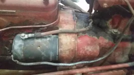
The blue cable goes to the positive clamp, which also grounded to the dash panel. Because it's a positive ground system...

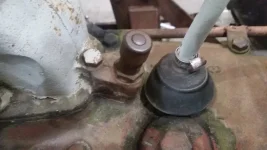
The red(ish) cable goes to one of the two terminals on the manually operated high amp starter switch. There is no solenoid... You hit the starter button, that thing that looks like a headlight dimmer switch in an old car, and assuming it's in neutral you physically push the contacts together.

20170411_173252.webp

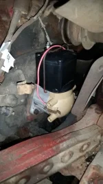
That said, I have no effin' clue what that tin can above it us but it's got wires connected to it.

20170411_173527.webp

:dunno:

The schematic for this conversion kit are for the 8N model which uses a regular type solenoid. :mad:

However the kit says it's for 9N, 2N and 8N models.
 

Back
Top